
1. OSI Seven-Layer Model
| |
| OSI Layer | Core Function | Key Devices/Components |
|---|---|---|
| Application Layer | Provides communication between applications | Browsers, FTP clients, SMTP clients |
| Presentation Layer | Data representation and transformation | Encryption, compression |
| Session Layer | Manages session connections | Session ID |
| Transport Layer | End-to-end communication | TCP, UDP |
| Network Layer | Routing across networks and IP address recognition | Routers, switches |
| Data Link Layer | Frame transmission and MAC address recognition | Network cards, switches |
| Physical Layer | Bitstream transmission | Wires, fiber optics |
2. Differences between HTTP/1.1 and HTTP/2
| Feature | HTTP/1.1 | HTTP/2 |
|---|---|---|
| Transmission Overhead | Text-based transmission, higher overhead | Binary stream transmission, lower overhead |
| Multiplexing | Sequential loading of resources, one resource blockage affects subsequent resources | Multiple data streams can be sent simultaneously over a single TCP connection, without blocking each other |
| Server Push | Not supported | Supported, the server can push content before the client requests it |
| Header Compression | Not compressed or simple compression, redundant information | Uses HPACK compression, reduces redundancy, improves loading speed |
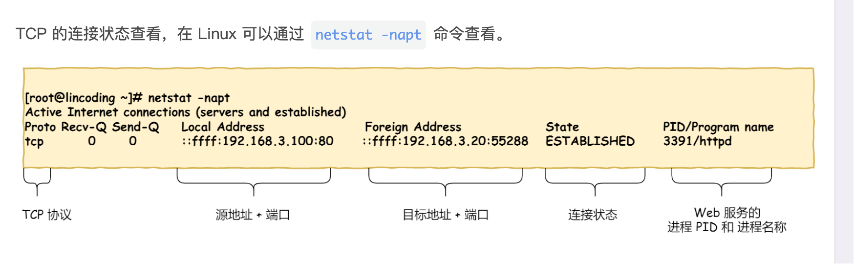
3. TCP Connection States
4. Why TCP is Three-Way Handshake
Because three-way handshake is necessary to ensure that both parties have the ability to receive and send.
Why Not 2-Way Handshake
Suppose we need two handshakes:
- Client sends SYN
- Server returns ACK
- If there is a delay or packet loss in the network, an old SYN packet may remain in the network.
- The server receives the lingering SYN and mistakenly believes that the client wants to establish a new connection, and returns an ACK.
- The client receives the ACK and mistakenly believes that the connection has been established, and continues to send data.
- The server receives the data and mistakenly believes it to be traffic from a new connection, and handles it incorrectly.
Why Not 4 Times or More?
Three handshakes are sufficient to establish a connection; four or more handshakes would increase complexity and waste resources.
5. DNS Resolution Process
- Local host mapping (highest priority, returns directly if there is a record)
- Client cache (browser cache, IOS cache)
- DNS Resolver (/etc/resolv.conf specifies the system query DNS server, usually the local router or operator DNS)
- DNS Iterative Query Process (root domain server -> top-level domain server -> authoritative domain server (e.g., route 53))
- Returns to the client
6. Cookie, Session, Token
- Different storage locations
- Cookie, Token are stored on the client side, while Session is stored on the server side
- Different data security
- Cookie is stored on the client side and is easily stolen, not secure
- Session is stored on the server side and is associated with different users’ sessions through a Session ID between the client and server, which can avoid exposing sensitive data directly
- Token is usually generated using an encryption algorithm, has a short expiration time, and is one-way and irreversible, which can provide higher security.
- Different cross-domain support Cookie and Session do not support cross-domain transmission, but Token can easily implement cross-domain. Because Token is stored in the client’s localStorage or sent as part of the request header to the server, the Token information transmission between different domains is usually not affected.
- Different state management
- Cookie is stored on the client side and can be directly manipulated by the client for state management.
- Session is stored on the server side, and the server identifies different user sessions through Session ID.
- Token is generated on the client side and needs to be carried by the client in each request for identity verification.
- Different application scenarios
- Cookie is usually used to store user login status, remember user preferences, and maintain login status.
- Session is suitable for scenarios where user state needs to be stored on the server side, such as shopping carts, form submissions, etc., that need to track user states.
- Token is suitable for scenarios where identity verification needs to be performed between the client and server, such as API access control, single sign-on (SSO), mobile application authentication, etc.
7. HTTP Status Codes and Reasons
Some frequently examined status codes
301 Moved Permanently: The requested resource has been permanently moved to a new location. Often used for domain switching.
302 Found: Temporarily redirected, the requested resource is temporarily moved to a new location. (Browsers often use it for login redirection).
403 Forbidden: Insufficient permissions, or has a Token but no permissions.
404 Not Found: The requested resource does not exist.
502 Bad Gateway: The upstream service (Nginx → Application) returns an invalid response.
504 Gateway Timeout: The upstream service response is too slow (Nginx → Backend timeout).
8. Linux Network Packet Loss Troubleshooting
Troubleshooting Chain: Application → System → Network Stack → Network Card → Cloud Side → External Link
Application Layer Packet Loss
- Check application logs for exceptions or error information. (Timeouts, link failures, interface qps spikes)
- Simulate client curl/wget to directly test
- Use tcpdump to capture packets: sudo tcpdump -i eth0 host
-w app.pcap
System Layer Packet Loss
Check network card statistics: ethtool -S eth0
Metric Meaning Notes rx_droppedReceive dropped packets NIC or kernel queue full rx_errorsReceive errors CRC, frame errors tx_errorsTransmission errors Not sent out rx_no_bufferRing buffer insufficient High pressure common rx_over_errorsReceive queue overflow System bottleneck Check Linux network stack layer packet loss: netstat -s
Check kernel parameters
1
2
3
4
5
sysctl net.core.rmem_default sysctl net.core.wmem_default sysctl net.core.netdev_max_backlog sysctl net.ipv4.tcp_rmem sysctl net.ipv4.tcp_wmem
Network Card Queue (Ring buffer) Packet Loss ethtool -g eth0
CPU/Interrupt
- Check the network card configuration parameters to ensure that there are no settings that cause packet loss.
- Use tools like
ethtoolto view the network card’s statistical information to confirm if there is any packet loss.
Network Path Packet Loss (Common in cloud side) mtr -rwzbc 100
Target End Packet Loss (Opposite entry is full)
| |
9. Long Connections, Short Connections, WebSocket Differences and Use Cases
Short Connections The connection between the client and server is closed immediately after each request is completed. This is the default behavior in HTTP/1.0.
- For one-time requests, such as retrieving static resources (HTML, CSS, images, etc.).
- For applications that do not require frequent interaction, short connections are simple and easy to use.
Long Connections Refers to a TCP connection in which multiple requests and responses can be made and received without the need to frequently establish and close connections. This is the default behavior in HTTP/1.1.
- For applications that require frequent interaction, such as online chat, real-time data streams (mysql, redis, etc.).
- Suitable for scenarios that need to maintain sessions, such as shopping cart operations on e-commerce websites.
WebSocket A protocol that allows full-duplex communication over a single TCP connection, allowing the server to send data to the client actively. Supports two-way communication.
- For real-time applications, such as online games, stock market quotes, social media instant messages, etc.
- Suitable for applications that require immediate feedback, such as collaborative editing tools, online customer service, etc.
- For real-time communication between IoT (Internet of Things) devices.
10. How MAC Address and IP Address are Converted
ARP is used to find the MAC address through IP address and store the corresponding relationship in the ARP cache table.
Second-layer devices, send data frames
- The source host first sends a broadcast frame, carrying its IP address and MAC address, and also carrying the IP address to be searched.
- Other hosts receive it and if they find that the IP address is their own, they need to return their IP address and MAC address, unicast to the source host, and record the corresponding relationship in their own high-speed cache table.
- The source host receives it and records it in the high-speed cache table after receiving it.
11. Differences and Use Cases of LVS, Nginx, and HAProxy
- LVS is a load balancer based on the IP layer, working at layer 4 (Transport Layer) of the OSI model, and is mainly used for load balancing TCP and UDP traffic.
- Nginx is a high-performance web server and reverse proxy server that can also be used as a load balancer. It works at layer 7 (Application Layer) of the OSI model and is mainly used for processing HTTP and HTTPS requests.
- HAProxy is an open-source load balancer that works at layer 7 (Application Layer) of the OSI model and is mainly used for load balancing HTTP and HTTPS requests.